86-020-87542879
8-1304, Shipai West Road, Tianhe Dist., Guangzhou, Guangdong, China (Mainland)


Huawei TN12DCP 2-channel optical path protection board, US $ 1 - 1,500 / Piece, Guangdong, China (Mainland), Huawei, TN12DCP.Source from Guangzhou Kang Mai Communication Technology Co., Ltd. on Waimaotong.com.

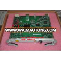
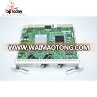
Huawei TN12DCP 2-channel optical path protection board
Version Description
The DCP board has three functional versions: TN11, TN12, and TN13. Together these three versions are referred to as the DCP board unless otherwise specified.
Mapping Between the Board and OptiX OSN 9800 Universal Platform Subrack
The following provides the board(s) supported by the product. However, the availability of the board(s) is subject to PCNs. For PCN information, contact the product manager at your local Huawei office.
Board | Initial Version | 9800 Universal Platform Subrack |
TN11DCP | V100R001C01 | Supported |
TN12DCP | V100R001C01 | Supported |
TN13DCP | V100R001C20SPC360 | Supported |
Variants
The table below describes the available variants of the DCP board.
Board | Variant | Description |
TN11DCP | 02 | Supports multi-mode optical modules. |
TN12DCP | 01 | Supports single-mode optical modules. |
04 | Supports single-mode optical modules. | |
TN13DCP | 01 | Supports the single-mode optical module. |
Differences Between Versions
Function:
The TN11DCP board supports multi-mode optical modules.
The TN12DCP/TN13DCP board supports single-mode optical modules.
Specifications:
The power consumption varies according to the board version being used. For details, see DCP Specifications.
Substitution Relationship
Board | Substituted By | Substitution Rules |
TN11DCP | None | - |
TN12DCP | TN13DCP | The TN13DCP board can be created as 12DCP on the NMS to substitute for the TN12DCP board. The board substitution does not require software upgrade. NOTE: When a system control board is installed in slot IU2 of the 9800 Universal Platform Subrack , the TN13DCP board cannot be installed in slot IU1. Therefore, if a TN12DCP board is installed in slot IU1 and a system control board is installed in slot IU2 of the 9800 Universal Platform Subrack , the TN13DCP board cannot substitute for the TN12DCP board. |
TN13DCP | None | - |
Update Description
This section describes the hardware updates in V100R001C01 and later versions as well as the reasons for the updates. Any product versions that are not listed in the document means that they have no hardware updates.
Hardware Updates in V100R002C10&V100R002C00SPC810
Hardware Update | Reason for the Update |
Added the description of whether the DCP boards support ASON. | The function is enhanced. |
Hardware Updates in V100R001C20SPC360
Hardware Update | Reason for the Update |
Added the TN13DCP01 board. | The board is manufactured using an optimized engineering process, and the board specifications are adjusted. |
Hardware Updates in V100R001C01
Hardware Update | Reason for the Update |
Added the TN11DCP02, TN12DCP01 and TN12DCP04 boards. | The TN11DCP02, TN12DCP01 and TN12DCP04 boards must be used to implement intra-board 1+1 protection and client 1+1 protection. |
Application
As an optical protection unit, the DCP board provides intra-board 1+1 protection and client 1+1 protection.
Figure 1 and Figure 2 illustrate the position of the DCP board in a WDM system.
Figure 1 Position of the DCP board in a WDM system (intra-board 1+1 protection)
NOTE:
When used for intra-board 1+1 protection, the DCP board does not support 2.5 Gbit/s OTUs.
Figure 2 Position of the DCP board in a WDM system (client 1+1 protection)
NOTE:
When the DCP board is used to provide client 1+1 protection, the working and protection OTUs must be installed in different subracks or chassis.
Functions and Features
The DCP board provides intra-board 1+1 protection and client 1+1 protection.
Table 1 describes the functions and features of the DCP board.
Table 1 Functions and features of the DCP board
Function and Feature | Description |
Basic function | Provides protection for two signals: Intra-board 1+1 protection: The board offers protection for the services of two OTUs that do not have the dual-fed and selective receiving function. Client 1+1 protection: The board offers protection for two client services by working with two OTUs: one as the working OTU and the other as the protection OTU. |
Protection mechanism | Dual-fed and selective receiving. (At the transmit end, the protected signal is dually fed to the working and protection paths. At the receive end, the working or protection signal is selected if it has the higher power level.) |
Optical-layer ASON | Supported |
Working Principle and Signal Flow
The DCP board consists of an optical module, control and communication module, and power supply module.
Figure 1 shows the functional modules and signal flow of the DCP board.
Figure 1 Functional modules and signal flow of the DCP board
Signal Flow
One DCP board provides protection for two optical signals. The DCP board processes the two optical signals identically. This following describes the service flow of one optical signal.
Transmit direction
The DCP board receives a protected signal through the TI1 port and uses splitter 1 to split the signal into two identical signals. Then the two optical signals are directed out to the working and protection fibers (paths) through the TO11 and TO12 ports.
Receive direction
The DCP board receives the working and protection signals through the RI11 and RI12 ports, respectively. Then the working and protection signals are sent to optical switch 1, and a sample of each signal is directed to the power detection module to detect their power levels. The control and communication module compares the detected power levels of the two signals and enables optical switch 1 to select the signal with the higher power level. Lastly, the selected signal is output through the RO1 port.
Module Functions
Optical module
The optical module performs dual-fed and selective receiving of two protected signals.
Transmit direction
Splits each of the two signals into two identical signals and directs them onto the working and protection paths.
Receive direction
Receives two working and protection signals while providing a sample of each of the signals to the power detection module to detect the signal power levels. The power detection module reports the detection results to the control and communication module to compare the power levels of the working and protection signals. Then each optical switch inside the optical module selects the signal with the higher power level and directs it out the corresponding port.
Control and communication module
Compares the power levels of the working and protection signals and enables the optical switch to select the signal with the higher power level.
Controls board operations.
Controls the operations on each module of the board according to CPU instructions.
Collects information about alarms, performance events, working states, and voltages from functional modules on the board.
Communicates with the SCC board.
Power supply module
Converts the DC power supplied from the backplane into appropriate power required by each module on the board.
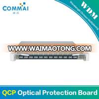
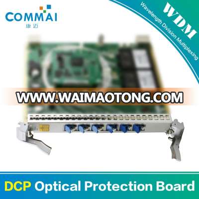
Front Panel
There are indicators and interfaces on the front panel of the DCP board.
Appearance of the Front Panel
Figure 1 shows the front panel of the DCP board.
Figure 1 Front panel of the DCP board
Indicators
Four indicators are present on the front panel:
Board hardware status indicator (STAT) - triple-colored (red, green, yellow)
Service active status indicator (ACT) - dual-colored (red, green)
Board software status indicator (PROG) - dual-colored (red, green)
Service alarm indicator (SRV) - triple-colored (red, green, yellow)
For details about these indicators, see Board Indicators.
Interfaces
Table 1 describes each interface on the DCP board.
Table 1 Interfaces on the DCP board
By leveraging our strong R&D capabilities, comprehensive technical expertise, and continuous technical innovations, Commai is committed to building an open, flexible, resilient, and secure platform in the Network and communication industry to orchestrate a sustainable, multi-win ecosystem. Following the guiding principle of Business-Driven ICT Infrastructure (BDII), Commai teams up with customers and partners in joint innovations. By doing so, we help customers from a variety of industries – including government and public sectors, finance, energy, transportation, and manufacturing – stay ahead in the new ICT era, and jointly build a Better Connected World.
1.Good Reply: Your inquiry related to our products or price will be replied within 24 hours.
2.OEM&ODM: We can help you to design and put your good idea into products.
3.Warranty: 1-years warranty.
4.Technology support: On-site technical support, Telemaintenance, Free call and E-mail technology supports.
5.Training service support: Provide free training service on installation and debugging.
1.Can we get a lower price?
Yes,price is not a problem,everything could be negotiated based on the quantity.
2.What is your MOQ?
No MOQ for any sample test.
3.OEM,ODM Service is available?
Yes, Commai have strong ability to offer customers ODM&OEM products of highest quality.
And it will requirement about your quantity.